
1. Introduction
Lever hoists—also known as ratchet lever hoists or come-alongs—are among the most versatile manual lifting tools used across industries such as construction, shipbuilding, mining, utilities, and transportation. Their primary advantage lies in their compact design, portability, and ability to lift, pull, or secure loads in any direction.
A crucial aspect of lever hoist safety and performance is its maximum lifting capacity and Working Load Limit (WLL). These ratings define the maximum weight the hoist can safely handle under specified conditions. Understanding what determines these limits—and how to interpret them correctly—is essential for preventing accidents, ensuring equipment longevity, and maintaining compliance with international safety standards.
This essay explores the engineering, material, and operational factors that determine a lever hoist’s lifting capacity and WLL. It also explains how users should interpret these ratings in real-world applications to maintain safe and efficient lifting operations.
2. Understanding Maximum Lifting Capacity and Working Load Limit
Before examining the factors that determine capacity, it is important to clarify the terms commonly used:
-
Maximum Lifting Capacity (Rated Capacity):
The absolute maximum load that a lever hoist can lift under ideal conditions as defined by the manufacturer. It is a theoretical design limit and typically includes a built-in safety factor. -
Working Load Limit (WLL):
The maximum load that should be applied during regular operation. It represents the load value at which the hoist can safely function without risk of failure. The WLL is derived by dividing the Minimum Breaking Load (MBL) by a Safety Factor (SF).WLL=MBLSafety Factor\text{WLL} = \frac{\text{MBL}}{\text{Safety Factor}}
-
Safety Factor:
A multiplier applied to account for uncertainties such as dynamic forces, material fatigue, and manufacturing tolerances. For manual hoists, typical safety factors range from 4:1 to 5:1, depending on the standards followed (e.g., ASME B30.21, EN 13157, or JIS B8819).
These values are determined through rigorous engineering analysis, testing, and certification to ensure the hoist can safely handle both static and dynamic loads throughout its service life.
3. Engineering Factors Determining Lifting Capacity
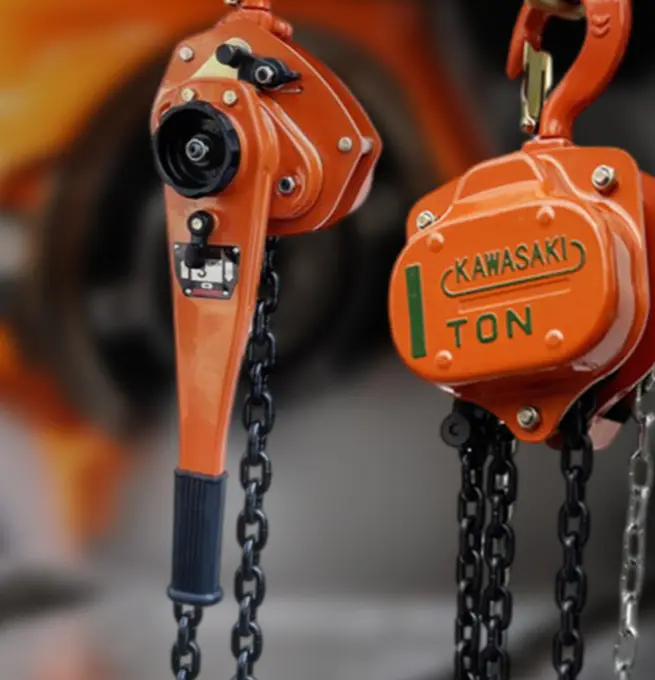
3.1 Load Chain Strength
The load chain is one of the most critical components influencing lifting capacity.
-
Material: High-grade alloy steel (usually Grade 80 or Grade 100) is used due to its high tensile strength, fatigue resistance, and toughness.
-
Heat Treatment: Processes such as quenching and tempering enhance the microstructure, improving resistance to elongation and wear.
-
Link Dimensions: The chain’s pitch, diameter, and cross-sectional area directly affect the load-bearing capacity. Even minor dimensional deviations can significantly reduce strength.
Manufacturers test chains through tensile load testing and proof-load verification to ensure consistency. The breaking strength of the chain largely determines the hoist’s upper capacity limit.
3.2 Gear Train Design
The gear system amplifies the operator’s manual force. The gear ratio determines the mechanical advantage:
-
A higher gear ratio provides greater lifting power with less manual effort but reduces lifting speed.
-
A lower ratio increases lifting speed but requires more force.
Gear materials—typically hardened steel or precision-machined bronze alloys—must withstand cyclic loading without deformation. The tooth profile and surface finish affect efficiency and fatigue life, directly influencing how much load can be lifted safely.
3.3 Lever and Ratchet Mechanism
The ratchet-and-pawl assembly controls incremental movement and prevents backsliding. Its design dictates the hoist’s ability to hold a load under static conditions.
Key parameters include: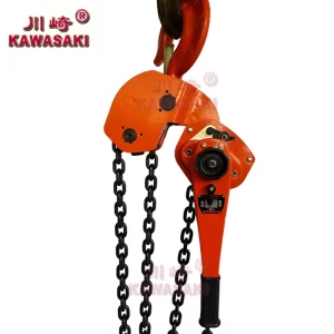
-
Tooth geometry (for optimal locking under load).
-
Pawl strength and engagement angle.
-
Lever length (which determines input torque).
If the ratchet or pawl fails, the entire load can fall, so their rated capacities are designed well above the chain’s WLL to ensure redundancy.
3.4 Load Brake System
Most lever hoists use a friction disc brake or mechanical load brake that automatically engages when the lever stops moving. The brake’s torque capacity must exceed the torque generated by the maximum rated load.
Factors influencing brake performance include:
-
Friction material composition.
-
Brake spring tension.
-
Wear resistance and heat dissipation.
Braking systems are tested under overload and sustained holding conditions to verify their contribution to the overall WLL.
3.5 Hooks and Suspension Components
The load hook and top hook are critical stress points. These components are forged from high-strength steel and designed with gradual curves to distribute stress evenly. Hooks are typically fitted with safety latches and have a yield-before-break design, meaning they deform visibly before fracturing—providing a warning before catastrophic failure.
The hook’s throat opening, cross-sectional area, and load alignment directly influence lifting capacity.
4. Material and Manufacturing Quality
The consistency of materials and manufacturing precision are vital to achieving rated capacity.
4.1 Metallurgical Quality
All structural parts—such as the lever, gears, and body frame—must meet specific metallurgical standards. Impurities, inclusions, or voids in steel can lead to stress concentrations and premature fatigue.
4.2 Heat Treatment and Surface Hardening
Gears and ratchets are surface-hardened through carburizing or induction hardening. Chains and hooks are tempered for balanced strength and ductility. Improper heat treatment can cause brittleness, which reduces WLL drastically.
4.3 Dimensional Tolerances
Precision machining ensures smooth gear meshing, proper pawl engagement, and consistent chain pitch. Excessive tolerances can create uneven load distribution and reduce mechanical efficiency.
4.4 Quality Assurance Testing
Before certification, lever hoists undergo:
-
Proof Load Tests: Usually at 1.25 to 1.5 times the WLL to confirm structural integrity.
-
Breaking Load Tests: To determine the MBL.
-
Endurance Tests: Simulating long-term cyclic use.
Only units passing these tests can display rated capacities and WLL markings.
5. Environmental and Operational Factors
5.1 Temperature and Corrosion
Extreme cold can cause steel to become brittle, while high temperatures may reduce tensile strength. Corrosive environments (marine, chemical plants) can weaken components or increase friction. Stainless or coated chains and sealed mechanisms are used for these conditions, but their capacity may be derated.
5.2 Orientation and Direction of Load
Lever hoists can operate horizontally, vertically, or at angles. However, lifting at an angle introduces side loading, which places uneven stress on the hooks and body. Manufacturers typically rate the WLL for vertical lifts only—side or diagonal pulls can reduce safe capacity by 15–30%.
5.3 Dynamic and Shock Loading
Static load ratings assume gradual application of force. In reality, jerks or rapid starts can create dynamic loads exceeding the WLL by several times. Hence, operators are instructed to lift smoothly and avoid shock loading to maintain safety margins.
5.4 Wear and Maintenance
Regular wear of chain links, gears, and brake discs reduces effective capacity. Dirt, rust, or lack of lubrication increases friction, causing premature stress and reduced mechanical efficiency. Routine inspection and maintenance are therefore integral to maintaining WLL integrity.
6. Calculation and Certification of WLL
Manufacturers establish the WLL through controlled testing and compliance with international standards.
6.1 Testing Procedures
-
Breaking Load Test: Determines the ultimate load before failure.
-
Proof Load Test: The hoist is loaded to a value greater than the WLL (typically 125%–150%) and must operate normally afterward.
-
Operational Test: The hoist is run through multiple lifting cycles to confirm brake function and chain integrity.
6.2 Standards and Certification
Common standards include:
-
ASME B30.21 (U.S.)
-
EN 13157 (Europe)
-
JIS B8819 (Japan)
-
ISO 12100 / ISO 16881 (International Safety Standards)
These specify design requirements, testing methods, and labeling practices. Hoists passing these tests are labeled with the WLL, manufacturer ID, serial number, and inspection date to ensure traceability.
7. Interpreting WLL in Practical Applications
Understanding how to interpret WLL is essential for safe field operation.
7.1 Never Exceed the WLL
Operators must never attempt to lift loads exceeding the stated WLL. Doing so can lead to deformation, brake failure, or chain fracture. Overloading also voids manufacturer warranties and legal certifications.
7.2 Factor in Load Dynamics
Real loads are rarely static. If a load might swing, jerk, or drop slightly during lifting, a dynamic load factor should be applied. For instance, if shock loads are expected, the effective working load should be 80% or less of the WLL.
7.3 Consider Load Distribution
If multiple hoists are used to lift a single object, the total load must be evenly distributed. Unequal sharing can cause one hoist to exceed its WLL even if the combined capacity seems adequate.
7.4 Adjust for Environmental Conditions
For corrosive or high-temperature environments, apply derating factors as specified by the manufacturer. For example:
-
Marine or chemical exposure: Derate by 10–15%.
-
High-temperature (>200°C) operations: Derate by up to 25%.
7.5 Inspection and Record Keeping
Operators must inspect chains, hooks, and brakes before each use. Any sign of elongation, bending, or cracks requires immediate removal from service. Records of inspections and maintenance help ensure the hoist continues to meet its rated WLL over time.
8. Safety and Legal Implications
Failure to adhere to WLL can have severe consequences:
-
Equipment Damage: Permanent deformation or breakage.
-
Personal Injury or Fatality: Falling loads can endanger nearby workers.
-
Legal Liability: Violations of OSHA or regional safety regulations may result in fines or criminal charges.
Therefore, safety training should emphasize understanding load charts, interpreting labels, and recognizing environmental limitations.
9. Technological Advances Affecting WLL Determination
Modern engineering and digital technologies are improving accuracy and safety in determining and monitoring WLL:
-
Finite Element Analysis (FEA): Simulates stress distribution to optimize design.
-
High-Performance Materials: Use of Grade 120 chains or composite levers increases capacity while reducing weight.
-
Digital Load Monitoring: Smart lever hoists with built-in sensors measure real-time load tension, warning operators when nearing WLL.
-
Corrosion-Resistant Coatings: Zinc-nickel and ceramic coatings help maintain mechanical integrity over longer service periods.
These innovations not only refine WLL accuracy but also enhance user confidence in field applications.
10. Conclusion
The maximum lifting capacity and Working Load Limit (WLL) of a lever hoist are the result of precise engineering, rigorous testing, and strict adherence to safety standards. These ratings are determined by an interplay of factors—material strength, gear ratio, brake torque, hook design, and manufacturing quality—all backed by proof-load and breaking-load verification.
In practical applications, WLL must be viewed as an absolute operational ceiling, not a guideline. Operators should always consider real-world conditions such as dynamic loading, environmental factors, and wear when planning lifting operations. Adhering to WLL ratings not only ensures equipment reliability but also safeguards lives, property, and productivity.
Ultimately, understanding and respecting the principles behind WLL transforms lever hoist use from a simple mechanical task into a disciplined engineering practice—one that balances human effort, material science, and mechanical precision to achieve safe and efficient lifting.