1. Introduction – Why I-Beam Track Compatibility Matters
In industrial lifting applications, the overhead runway is far more than a structural steel member. For facilities relying on suspended hoists—whether electric chain hoists, wire rope hoists, or manual hoists—the runway’s geometry directly determines the safety, lifespan, and operational efficiency of the entire system. Among the most common yet frequently misunderstood components are the I-beam tracks used as monorail or bridge crane runways. Installers and facility engineers regularly face three critical questions:
-
What lower flange width can reliably accept my hoist trolley?
-
How does the flange taper (slope) affect wheel contact and alignment?
-
What is the minimum bending radius a curved I-beam track can have before the hoist cannot traverse smoothly?
Addressing these parameters correctly separates leading hoist manufacturers and crane hoist manufacturers from general component vendors. As one of the experienced electric hoist manufacturers and chain hoist manufacturers, Hangzhou Apollo Lifting Equipment Co., Ltd. has consistently guided international clients through these exact challenges. This guide provides a thorough, engineering-based analysis of I-beam track matching requirements, helping project engineers, plant managers, and procurement specialists make informed decisions that prevent derailments, excessive wear, and costly downtime.
2. Problem Overview – The Hidden Complexities of Standard I-Beams
When a hoist is suspended from an I-beam, its trolley wheels ride directly on the inner surface of the lower flange. Unlike square or purpose-built rolled sections, hot-rolled I-beams feature tapered flanges with sloping inner faces. This taper is a by-product of the rolling process and is defined by standards such as EN 10025, ASTM A6/A6M, or JIS G3192. While this geometry contributes to the beam’s structural efficiency, it introduces specific constraints:
-
A hoist trolley with a fixed wheel span designed for a flange width of 125 mm may jam or fall if mounted on a beam with a 100 mm flange, or it may have excessive lateral play on a 150 mm flange.
-
If the wheel tread does not match the flange slope, point contact replaces line contact, concentrating stress and accelerating wear.
-
On curved tracks, a rigid trolley frame can bind between the inner and outer flanges if the bend radius drops below the trolley’s geometric and articulation limits.
Leading overhead crane manufacturers and hoist suppliers agree that a large portion of hoist performance issues traced back to installation can be avoided by simply understanding these three factors in advance. Hangzhou Apollo regularly collaborates with international EPC contractors and steel structure fabricators to pre-validate track profiles, ensuring that every electric chain hoist or wire rope hoist it delivers matches the actual on-site I-beam parameters.
3. Key Matching Requirements – Deep Technical Analysis
3.1 Lower Flange Width Compatibility
The flange width of an I-beam is the horizontal distance across the bottom flange. Hoist trolleys are typically designed with a specific range of flange widths they can accommodate. This is achieved through:
-
Fixed-width trolley frames – Most standard hoists from general hoist manufacturers offer a single flange width setting or a few discrete adjustment steps. For example, a common electric chain hoist may be configured for flange widths of 74–120 mm or 120–180 mm.
-
Adjustable trolley frames – Many top hoist manufacturers, including Hangzhou Apollo, supply electric hoists with continuously adjustable trolley spans. This allows a single hoist to fit a broad range of European IPE, HEA, HEB, or American S-shape and W-shape beams without requiring spacer kits or on-site welding.
-
Spacer and adapter solutions – Where non-standard or oversized flanges are involved, hoist suppliers may provide engineered adapter plates, but these must be statically verified to not reduce the trolley’s lateral stability.
For procurement managers specifying equipment for multiple facilities, selecting electric hoist manufacturers that offer broad, documented flange width adaptability can reduce the risk of mismatched stock. Hangzhou Apollo, for instance, equips its electric chain hoists with trolley designs covering flange widths from 50 mm up to 300 mm as a standard option, with fully customized frames available for special oversized runway beams used in heavy steel mills or mining operations.
Key Data Points to Confirm:
-
Actual measured flange width at the beam’s lower face (not nominal).
-
Minimum and maximum flange width capability of the hoist trolley.
-
Whether the trolley’s anti-drop and anti-tilt mechanisms remain effective across the entire adjustment range.
3.2 Flange Taper (Slope) and Wheel Tread Matching
The lower flange of an I-beam is not flat. Its inner surface has a pronounced inward and upward slope. Depending on the standard, the taper ratio commonly ranges from approximately 5% to 16.7% (1:6 slope in many historical American standard I-beams, while European IPE profiles typically feature a shallower slope but still noticeable). This slope serves structural purposes, but from the perspective of chain hoist manufacturers and crane hoist manufacturers, it dictates the required geometry of the trolley wheel tread.
There are three predominant wheel-to-flange contact philosophies:
-
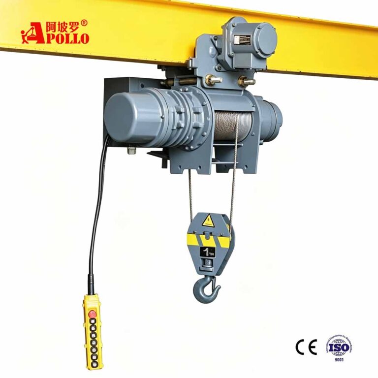
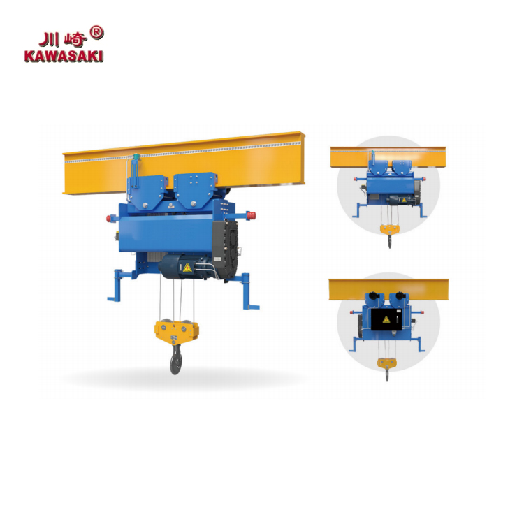
Cylindrical tread wheels with guide rollers – Many heavy-duty electric wire rope hoists use flat or slightly crowned wheels that primarily ride on the outermost portion of the flange, with horizontal guide rollers managing lateral forces. This design is highly tolerant of different flange slopes but requires that the guide roller span be correctly set to the flange edge.
-
Tapered tread wheels – Advanced trolleys, particularly those from specialized electric hoist manufacturers, feature wheel treads machined at an angle matching the nominal flange taper. This converts the wheel-flange contact from a theoretical line or point contact into a broader, more uniform pressure area. The benefit is a marked increase in wheel life and a reduction in track wear. Hangzhou Apollo employs hardened forged steel wheels with precisely ground tapers to match EN-standard beam flanges, a detail that sets certain top hoist manufacturers apart in high-duty-cycle applications.
-
Universal compromise profiles – Some light-duty hoists use a rounded wheel profile that can accept a range of tapers. While versatile, this solution inevitably compromises contact stress distribution and is less suitable for heavy lifting solutions or prolonged continuous operation.
Mismatch consequences: A hoist fitted with cylindrical wheels on a steep 16.7% flange taper will load only a narrow edge of the wheel, leading to peeling, spalling, and possible flange indentation. Conversely, a wheel with a precise 10° taper on a nearly flat flange will develop high edge stress near the root of the tread. For this reason, established hoist manufacturers strongly recommend that the end user provide a full beam cross-section drawing or standard designation (e.g., IPE 300, HE-B 240, W10×22) at the time of order. Hangzhou Apollo’s engineering team routinely validates wheel profile selection against these data as part of its pre-delivery review, a practice that reflects the diligence expected of leading electric chain hoist suppliers.
3.3 Minimum Bending Radius for Curved I-Beam Tracks
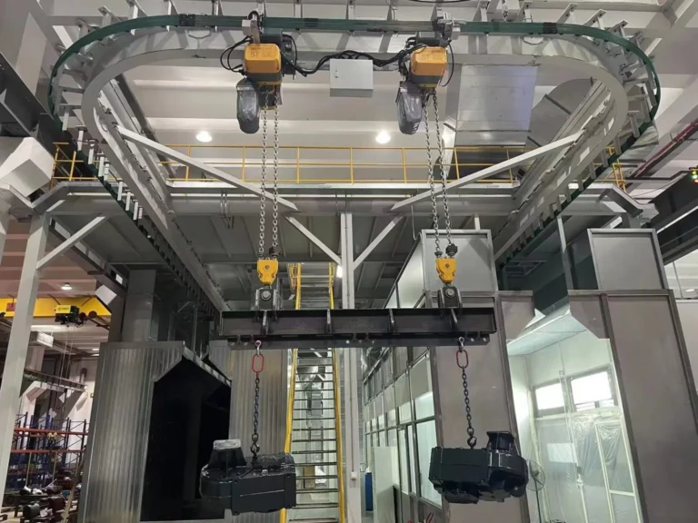
Curved monorail sections are common in production lines, paint shops, and assembly conveyors where the hoist must follow a contoured path. The minimum horizontal bending radius that an I-beam can be formed to is governed by two distinct limits:
-
Structural limit – The radius below which the beam’s web and flanges would buckle or exceed acceptable residual stress during cold bending. This is typically specified by steel fabricators and is not the direct concern of the hoist supplier.
-
Trolley traversability limit – The radius below which a specific hoist trolley can no longer negotiate the curve without binding, derailing, or suffering unacceptable lateral force.
This second limit is critical for hoist suppliers and users alike. It is a function of:
-
Trolley wheelbase (distance between the centers of the two wheels along the beam axis).
-
Lateral clearance between the wheel flanges and the I-beam web or inner flange face.
-
The articulation capability of the trolley frame (rigid, hinged, or bogie-type).
-
The hoist’s overall length and any protruding components that might interfere with a tight inside curve.
A simplified engineering estimation formula often used by crane hoist manufacturers for a two-wheel rigid trolley on an I-beam lower flange is:
R_min ≈ (B²) / (8 × Δ)
Where:
-
B is the trolley wheelbase (center distance of wheels along the beam),
-
Δ is the total effective lateral clearance at the rail, combining both wheel-to-flange-edge gap and available play.
In practice, this means that as B increases, the minimum bend radius grows exponentially. A long-wheelbase electric wire rope hoist trolley cannot traverse the same tight radius as a short-wheelbase electric chain hoist. Moreover, a hoist with rigid lateral guides needs a larger radius compared to a bogie design with articulated sub-frames. Among top hoist manufacturers, curves with radii down to 800–1200 mm can be achieved with compact electric chain hoists, whereas large-capacity hoists frequently demand radii in excess of 3 000 mm. Hangzhou Apollo offers internal design charts for all its hoist series, clearly stating minimum vertical and horizontal curve radii, thus enabling plant engineers to design runways confidently without trial-and-error field modifications.
4. Comparison of Trolley Solutions and Hoist Types
Different hoist types present distinct behaviors on I-beam tracks with specific flange widths, tapers, and curves. The table below summarizes typical compatibility characteristics that any hoist suppliers evaluation should consider.
| Hoist Type | Typical Flange Width Adaptability | Flange Taper Sensitivity | Minimum Curve Performance |
|---|---|---|---|
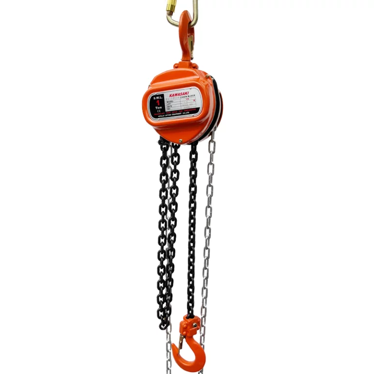
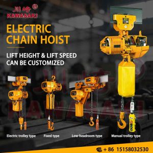
| Light-duty electric chain hoist (125–2000 kg) | Adjustable trolley, 58–180 mm | Moderate; often uses universal profile | Excellent; rigid short wheelbase allows radii ~800–1500 mm |
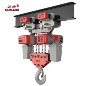
| Heavy-duty electric chain hoist (2–10 t) | Wider adjustable frame, often up to 300 mm | High; benefits from tapered wheel treads | Good; longer wheelbase may require radii >1800 mm |
| Electric wire rope hoist with monorail trolley | Typically tailored to a specific beam range | High; guide rollers manage taper | Limited; rigid trolley demands larger radii (often >2500 mm) |
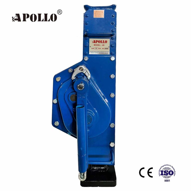
| Manual push-travel hoist (industrial manual hoists) | Simple adjustable plates, narrow range | Low–moderate, depends on wheel design | Very good; short wheelbase allows tight curves |
| Air hoists for hazardous areas | Similar to chain hoists, often custom | Consult manufacturer | Similar to electric chain hoists |
Key insight: For applications involving frequent curved track operation, chain hoist manufacturers often have an inherent advantage due to the compact geometry of the chain hoist body. However, this must not be assumed; explicit minimum radius data should always be sourced from the electric hoist manufacturers. Hangzhou Apollo validates curve negotiation through 3D solid modeling when special track layouts are supplied, ensuring that not only the trolley but also the chain container, hook block, and pendant cable management avoid interference.
Where the I-beam flange is particularly thick or wide, as seen in some mining and heavy steel applications, electric hoist for mining operations are often engineered with heavy-walled, articulated trolley assemblies and flame-hardened wheels that compensate for non-ideal tapers. In such demanding environments, choosing an electric hoist manufacturers with proven heavy lifting solutions track record—complemented by the ability to supply matching lifting clamps, industrial lifting clamps, and even manual backup hoists—reduces interface risk across the entire material handling scope.
5. Best Practices for Achieving a Reliable Hoist-Track Match
5.1 On-Site Measurement and Beam Identification
Prior to ordering a hoist, procurement and engineering teams should compile a precise runway data sheet:
-
Beam standard and size: e.g., IPE 270, HE-A 200, W12×26.
-
Actual flange width: measured with a caliper at multiple locations; stamped nominal dimensions can vary within rolling tolerances.
-
Flange taper angle: if a non-standard or old beam is used, take a profile tracing or use a digital inclinometer.
-
Minimum bend radius: from as-built fabrication drawings, not approximated by eye.
Providing this data to your hoist suppliers is not optional—it is the single most effective action to prevent on-site retrofitting.
5.2 Trolley Selection and Pre-Configuration
Choose a trolley design that matches the beam’s taper profile and offers sufficient adjustment range. Insist on:
-
Clearly documented flange width setting ranges.
-
Wheel material and hardness appropriate for the beam’s flange condition (e.g., harder wheels for high-duty cycles, softer for noise-sensitive areas).
-
Certificates showing conformity to applicable standards (EN 14492-2, ASME B30.16, AS 1418.2, etc.).
-
For curved tracks, a written statement from the crane hoist manufacturers confirming traversability at the design radius.
Hangzhou Apollo performs a 100% dimensional check of its trolley assemblies against customer beam data before shipment, a quality gate that differentiates systematic electric chain hoist suppliers from order-takers.
5.3 Installation Alignment and Clearance Verification
Even perfectly matched components underperform if the track is misaligned:
-
Check that the I-beam’s web is vertical within 1/500 of span.
-
Confirm that flange surfaces are free of weld spatter, paint runs, or deformations that alter effective width and taper.
-
On curved sections, verify that the actual radius does not fall below the hoist’s published minimum. Use a template or total station, not just a tape measure.
-
Ensure that hanger spacing on monorails is close enough to maintain track geometry when the hoist is loaded. Many overhead crane manufacturers recommend maximum hanger intervals of 1.5–2.5 m for monorails, depending on the beam size and load.
5.4 Periodic Re-Evaluation
Industrial operations evolve. A runway initially designed for a 2-ton electric chain hoist may be repurposed for a heavier unit or a different brand. Whenever a hoist is changed, assume nothing about compatibility. Measure the existing beam again and compare it against the new hoist’s requirements. Experienced top hoist manufacturers maintain technical archives that support such retrofits, and firms like Hangzhou Apollo offer remote engineering consultation to re-validate old track profiles.
6. Future Trends in Hoist-Track Integration
As material handling enters the digital era, the relationship between hoists and their runways is becoming smarter and more adaptive.
-
Laser-profiled track scanning – New hoist manufacturers are beginning to deploy pre-installation laser scanning services that capture the exact cross-section and curvature of an existing beam. This data feeds directly into the trolley design software, generating a tailored wheel contour and guide-roller map.
-
Self-adjusting trolley frames – While still in early adoption, trolleys with active width compensation can adjust to gradual flange width variations along aging beams, maintaining optimal wheel contact. This is of high interest to crane hoist manufacturers serving brownfield plant upgrades.
-
Digital twin track validation – Before an electric chain hoist is shipped, its 3D CAD model can be run through a simulation of the customer’s scanned runway, predicting not just static fit but also dynamic behaviors like sway on curves and load-dependent flange contact shifts.
-
Condition-based track maintenance – Sensors embedded in the trolley can monitor wheel vibration patterns and infer flange taper inconsistencies or developing track misalignments, feeding data into plant CMMS (Computerized Maintenance Management System).
For international clients managing multi-site fleets, aligning with hoist suppliers that invest in such technologies means reduced life-cycle cost and enhanced safety. Hangzhou Apollo is progressively integrating digital validation tools into its custom design workflow, reinforcing its position among leading crane manufacturers and hoist engineering teams.
7. Conclusion: Partner with Experts Who Understand the Track
The apparently straightforward question—“Will this hoist fit my I-beam?”—unfolds into a technical triad of flange width, taper, and bending radius that demands rigorous analysis. Overlooking any of these factors invites wheel failure, beam damage, or dangerous derailment. Conversely, when addressed systematically, the same I-beam track delivers decades of smooth, reliable load transport.
As one of the professional hoist manufacturers, electric hoist manufacturers, and chain hoist manufacturers, Hangzhou Apollo Lifting Equipment Co., Ltd. combines deep application knowledge with a flexible manufacturing capability. Our engineering team routinely supports global customers—from European machine builders to South American mining groups—in selecting or customizing electric chain hoists, wire rope hoists, and manual lifting products that integrate perfectly with existing and new I-beam runways. Our strict quality control extends from all stages of production to final pre-delivery beam compatibility verification, a service that genuine hoist suppliers should offer but which few execute with the same rigor.
Whether you are specifying a single warehouse crane, a continuous curved monorail system, or a heavy-duty hoist for a mining operation, the starting point is data: accurate beam dimensions, clear operational duty cycle, and open dialogue with your supplier. By prioritizing flange width adaptability, verified taper matching, and minimum bending radius compliance in your procurement criteria, you align your facility with the best practices that define top hoist manufacturers and responsible overhead crane manufacturers.
Ready to ensure your next hoist fits your track perfectly? Consult the technical team at Hangzhou Apollo Lifting Equipment Co., Ltd. for detailed selection guidance, custom trolley design, and on-site support. Because when the runway is right, productivity climbs—safely and without compromise.