A beam trolley fits safely when its adjustment range, wheel profile, and suspension geometry match the actual beam. Flange width is only the starting measurement. Check flange thickness, beam shape, edge condition, wheel spacing, wheel diameter, capacity, and load entry. Use this guide for a defensible fit check, then confirm the model against its drawing and specification.
The method applies to push, geared, or electric-hoist trolleys. A trolley that looks right in a photograph may still be wrong for a tapered flange, curved runway, or side pull. A fit calculation selects a candidate; it does not replace a rated inspection or manufacturer approval.
What the fit calculation must answer
A useful beam trolley fit calculator answers four separate questions. First, can the trolley physically pass over the flange without the side plates, spacers, or wheels binding? Second, do the wheels contact the beam on the intended running surfaces? Third, does the trolley remain stable when the hoist load is applied at the suspension point? Fourth, are the combined trolley, hoist, rigging, and load within the supporting beam and equipment ratings? Passing the first question does not prove the other three.
Record clear flange width, flange thickness, beam depth, flange slope, inside radius, edge condition, welds, splice plates, and obstructions. Record hoist dead weight and lifted load separately. For powered travel, add speed, starts per hour, runway length, and power arrangement.
OSHA overhead-crane requirements provide a US safety reference for crane components and operation; the selected trolley drawing, local code, and site engineering review remain controlling for the installation.
Measure the beam before choosing a trolley
Flange width and thickness
Measure usable running width between flange edges, not only the nominal beam designation. Check several runway points because paint, corrosion, repairs, or beam variation can change the opening. Measure flange thickness where wheels run. The required clearance and adjustment range must come from the trolley specification.
Beam shape and flange slope
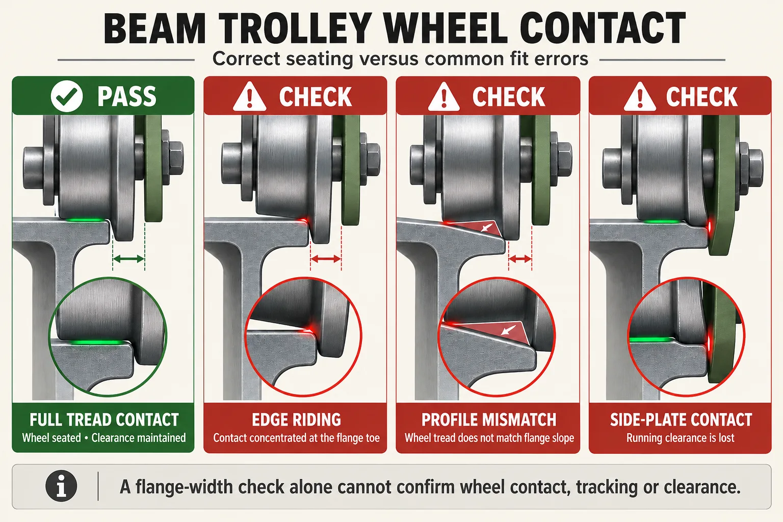
Identify whether the runway is a parallel-flange I-beam, a tapered-flange beam, a wide-flange section, a monorail profile, or a fabricated rail. Wheel tread and side-plate geometry that suit a parallel flange may not seat correctly on a taper. Record the flange angle and the inside radius when the manufacturer requests them. A square-edged drawing is not enough if the real beam has a rounded toe, a camber, or a transition at a splice.
Obstructions and runway continuity
Check beam end stops, brackets, clamps, bolts, stiffeners, runway joints, and changes in flange width. A trolley may fit at the survey point but fail to pass a joint or a low-clearance bracket. Also verify that the hoist hook, load chain, wire rope, and trolley frame have adequate clearance from the beam and adjacent equipment throughout the full travel path.
Wheel geometry: the part a width-only calculator misses
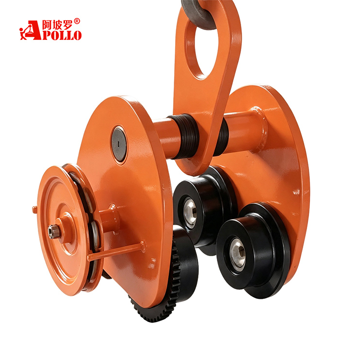
Wheels transfer the suspended load into the beam. Their diameter, tread width, tread profile, material, axle spacing, and side-guide arrangement affect contact pressure, rolling resistance, and tracking. A wheel that is too narrow can ride on an edge; a wheel that is too wide can contact a radius or a side plate before it reaches the intended running surface. A hard steel wheel and a polymer wheel can behave differently on painted, dirty, wet, or corrosive runways.
Use the wheel centerline and the trolley side-plate position to check that the load line remains between the wheel sets. If the hoist is offset, the trolley may see a twisting moment even when the nominal load is within capacity. For a powered trolley, check drive-wheel traction, guide rollers, and the effect of acceleration or braking. The manufacturer should confirm wheel loading and the permitted beam surface condition for the chosen configuration.
Use a worksheet for flange width and thickness, slope, radius, adjustment range, wheel dimensions, wheel spacing, suspended weight, capacity, and the narrowest runway point. Mark each field measured, specified, or pending confirmation.
A step-by-step beam trolley fit calculation
1. Measure the narrowest clear flange width and the thickest flange section on the complete travel path. Use the worst point, not the average.
2. Identify the beam profile. Confirm parallel or tapered flanges, running-surface condition, corner radius, camber, and any transitions.
3. Select a candidate trolley range. The adjustment range must cover the measured flange width while retaining the clearance stated by the manufacturer.
4. Check wheel contact. Confirm that each wheel sits on the intended running surface, with no edge riding, side-plate interference, or guide-roller conflict.
5. Check load path and capacity. Add the hoist, hook block, rigging, and lifted load as required by the equipment rating method. Confirm the beam and runway can carry the resulting wheel reactions.
6. Check movement. Test the tightest radius or joint, end stops, clearance to nearby equipment, and powered-travel forces. A static fit does not prove travel compatibility.
7. Document the decision. Keep the measured dimensions, marked-up beam sketch, trolley model, wheel option, adjustment setting, and approval record together with the installation file.
How Apollo trolley options relate to the worksheet
Apollo lists a dedicated CARGO TROLLEY category with multiple trolley families. The model should be selected from the measured beam and load path, not capacity alone.
For example, Apollo’s CRW cargo trolley page describes 3-12 ton models, 30 mm lifting height, operation in multiple units, and PU or steel wheel options depending on the model or requirement. Its CRA page describes CRA-4 to CRA-25 models, corresponding wheel quantities, and customizable wheel materials. These are product-family facts, not a universal flange-width range. Request the applicable drawing for the exact model and wheel configuration.
KAWASAKI CRW cargo trolley details can be reviewed alongside the beam survey when a CRW configuration is being considered.
When a project needs a different wheel material, unusual flange geometry, multiple trolleys, or a combined hoist and trolley arrangement, record those requirements explicitly. Apollo’s services and customization capability may be used to frame the technical request, but the final fit must be confirmed in the quotation, drawing, and installation instructions.
Common fit errors and how to prevent them
Using the nominal beam size is the most common error. Beam designations do not capture paint, corrosion, flange taper, local repairs, or the narrowest point on a runway. Measuring only one location creates the same risk. A second error is treating adjustment range as operating clearance. The trolley must be adjusted to the measured flange and the specified running clearance, not simply opened until it rolls.
Do not check only vertical capacity. Wheel reactions, side pull, skewing, acceleration, impact, and offset loads can govern. Stop if the trolley binds, walks, derails, or contacts the flange edge.
Procurement checklist for an RFQ
Send a dimensioned beam sketch or scaled photographs, narrowest and widest flange measurements, flange thickness and slope, radius, runway length, obstructions, dead weights, maximum load, load spectrum, travel method, wheel material, power supply, quantity, and location. Ask for allowable flange range, wheel geometry, adjustment procedure, clearance, wheel-load data, and tapered-beam restrictions.
For a model-specific review, contact Apollo’s technical team with the beam dimensions, drawing, load, and application conditions. A written fit check is more useful than a generic statement that a trolley is adjustable.
Conclusion
A beam trolley fit calculator should be a measurement and verification tool, not a single flange-width lookup. Start with the narrowest clear width, then add beam shape, flange thickness, corner radius, wheel contact, load path, runway continuity, and capacity checks. Apollo’s cargo trolley families provide several starting points, while the exact model, wheel option, adjustment, and installation must be matched to the measured beam and confirmed in the technical documentation.
FAQs
Can I choose a trolley from flange width alone?
No. Flange width is necessary but not sufficient. Beam profile, thickness, slope, corner radius, wheel geometry, load line, and obstructions also affect fit.
Does a wider flange always require a larger trolley?
Not automatically. The trolley must cover the measured width within its specified adjustment range and maintain the required wheel and side-plate clearance.
Are PU wheels suitable for every beam?
No. Wheel material depends on load, runway surface, environment, traction, and the product specification. Confirm the wheel option for the exact application.
What should I do if the beam is tapered?
Record the flange slope and inside radius, then request a model-specific compatibility check. Do not assume a parallel-flange trolley will seat correctly.