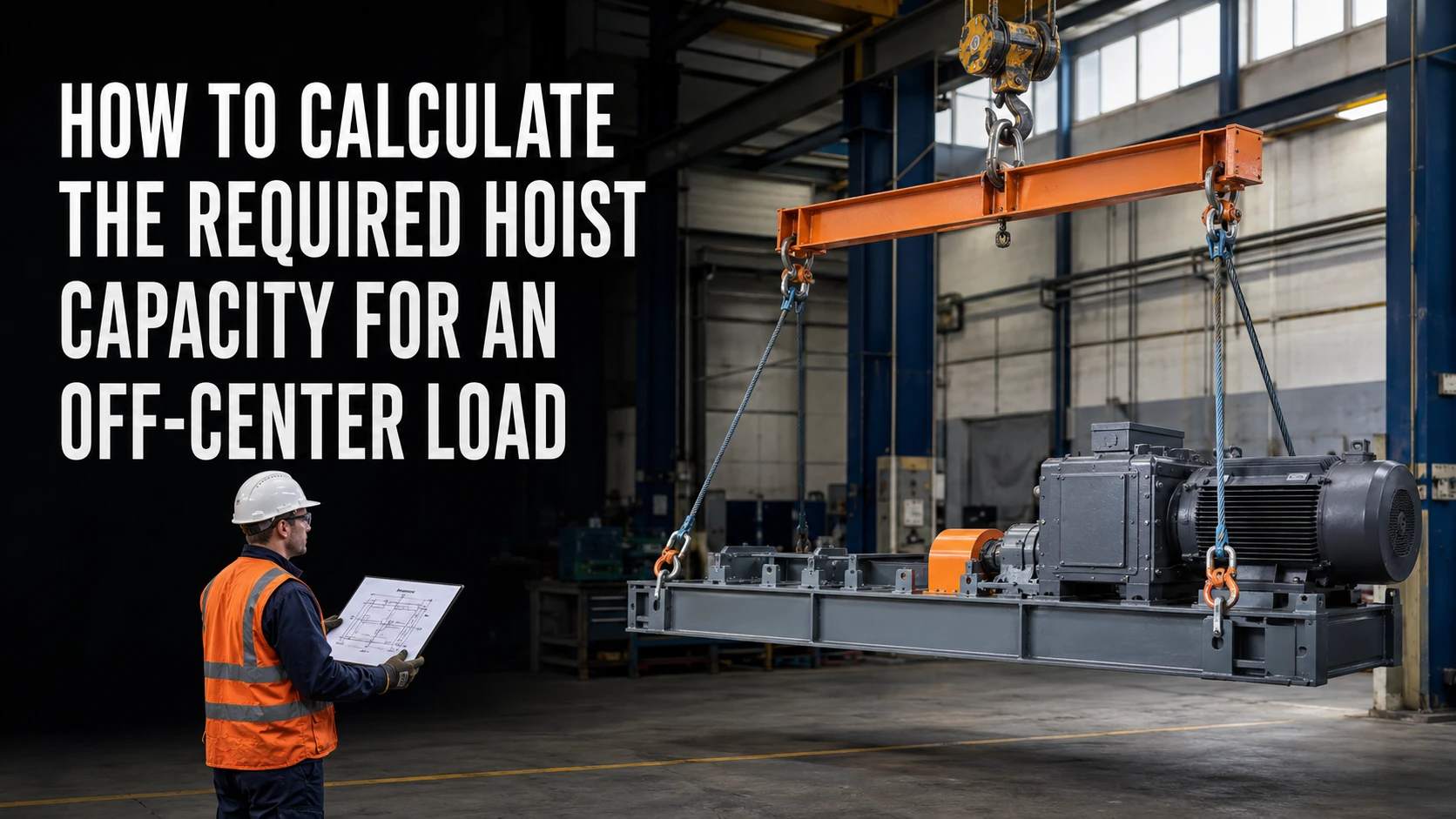
An off-center load changes more than the balance of a lift. It can shift the reaction carried by each lifting point, increase sling tension, introduce side force, and make the hoist, trolley, beam, or below-the-hook device the limiting component. To calculate the required hoist capacity, start with the total lifted weight, locate the center of gravity, resolve the support reactions, then check the complete load path for vertical, horizontal, and dynamic effects. The result is an engineering selection, not a simple addition of a percentage to the load tag.
What makes a load off-center
A load is off-center when its center of gravity does not lie directly below the hook or midway between the intended lifting points. The condition may come from uneven material density, an attached motor or gearbox, a partially filled vessel, an irregular frame, or lifting points that were not placed around the actual center of gravity. The load may look level on the floor and still rotate or tilt as soon as the rigging takes the weight.
The first control is positioning: whenever practical, place the hook vertically above the center of gravity before taking load. If the hook cannot be centered, treat the offset as a planned moment and calculate the resulting reactions. Do not rely on a trial lift to discover the imbalance after the hoist is already loaded.
Step 1: Define the design load
Record the mass of the payload and every item lifted with it: hook hardware, slings, shackles, spreader beams, lifting fixtures, and temporary attachments. Convert all values to one unit system. Let W be the total static lifted weight. Then identify the hoist’s rated capacity at the planned reeving, lift speed, duty, and operating environment. A hoist rating applies to its specified configuration; it is not automatically transferable to the crane bridge, trolley, beam, or rigging.
Next, identify foreseeable dynamic effects. Starting, stopping, snagging, load swing, wind, and impact can raise the force above W. Use the project or governing design basis for any dynamic factor, and document the source. If the factor is unknown, pause for a qualified lifting engineer rather than inventing a convenient multiplier.
Step 2: Locate the center of gravity and lifting points
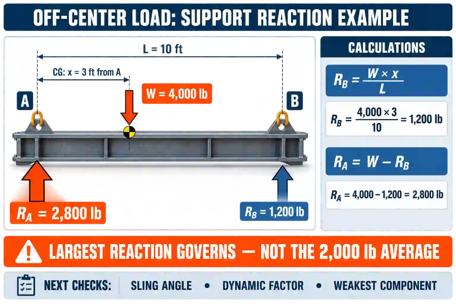
Create a plan-view sketch showing the center of gravity, hook line, lifting points, and distances. For a two-point lift with support spacing L, let x be the horizontal distance from support A to the center of gravity. Taking moments about A gives R_B = W x / L, and equilibrium gives R_A = W (L – x) / L. These values are only a first-order static model; they assume level supports, no friction, and a load path that actually shares force at the two points.
Example: a 4,000 lb load has lifting points 10 ft apart, and its center of gravity is 3 ft from point A. The ideal vertical reactions are R_B = 4,000 x 3 / 10 = 1,200 lb and R_A = 2,800 lb. Point A, not the average 2,000 lb, governs that support check. If the rigging geometry causes one leg to go slack or the load to rotate, the actual peak force can be higher.
Step 3: Account for sling angle and side force
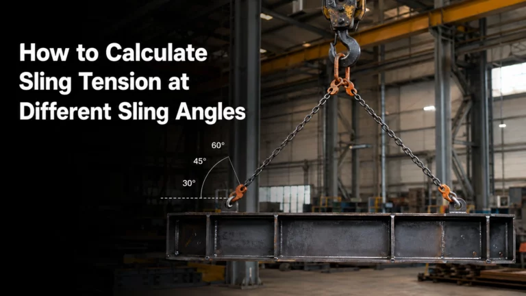
A sling does not carry only vertical force unless it is vertical. For a symmetric two-leg arrangement, a simplified leg tension is T = V / (2 cos theta), where V is the vertical load carried by the pair and theta is the sling angle measured from vertical. As theta increases, cos theta decreases and tension rises. With an off-center load, the two legs may have different angles and different vertical reactions, so calculate each leg from its own geometry.
Horizontal components must be resolved into the spreader, lifting points, shackles, and hook. A standard vertical hoist may be unsuitable if the arrangement creates side pull. Use a spreader or equalizing device only when its rated capacity, connection geometry, and load path are documented. A hoist should not be selected to absorb an unplanned horizontal force that belongs in the rigging design.
Step 4: Convert reactions into a hoist capacity check
| Check | Question | Selection implication |
| Vertical capacity | What is the maximum factored vertical force at the hoist connection? | The hoist, trolley, runway, and hook must each meet the applicable rating. |
| Rigging tension | Which sling or connection carries the largest component? | Select each sling, shackle, lug, and spreader for its own force, not the total load only. |
| Side load | Does the geometry create a horizontal component at the hook? | Reposition the hook or redesign the rigging; do not assume side pull is acceptable. |
| Stability | Will the load rotate, tilt, or contact an obstruction? | Use a controlled test lift and a written lift plan before full travel. |
Step 5: Add operational and structural limits
The required hoist capacity is governed by the weakest verified element. Check the hoist’s rated load, brake, hook, rope or chain, reeving, and duty class, then check trolley wheel loads, runway beams, end stops, support steel, lifting lugs, slings, shackles, spreaders, and the load itself. A hoist with enough nameplate capacity can still be the wrong choice if the supporting structure or connection cannot carry the off-center reaction.
Review clearances and motion as well. An offset load can sweep sideways during travel, contact a column, or transfer force into a guide. Define the lift path, exclusion zone, communication method, and stop points. Use a low-speed test lift only within the approved plan, keeping people clear and stopping immediately if the load tilts, binds, or shows unexpected movement.
How to document the calculation
A useful lift calculation package includes a dimensioned sketch, total lifted weight, center-of-gravity assumptions, support spacing, reaction equations, sling angles, connection forces, dynamic design basis, equipment ratings, and acceptance checks. Attach the hoist outline drawing and the rigging inspection status. Record what is known, what is measured, and what must be confirmed before release.
Apollo offers electric chain, electric wire rope, winch, and specialty hoists in its electric hoist product range. For an off-center application, the relevant product is the exact model and configuration, not the category name. The electric wire rope hoist category can be a starting point when lift, capacity, or duty leads to a wire-rope arrangement, subject to drawing review.
When the geometry is unusual, Apollo’s services and customization support may help organize a model-specific fit check. Provide the load sketch, center-of-gravity location, lifting points, required speed, duty, environment, and any existing crane or runway data.
Conclusion
To calculate required hoist capacity for an off-center load, calculate the total lifted weight, locate the center of gravity, solve the support reactions, resolve sling angles and horizontal components, and check every part of the load path. The largest reaction, not the average reaction, often controls. Apply the approved dynamic basis, verify the supporting structure, and document a controlled test lift. A model-specific drawing review is essential before ordering or operating the hoist.
FAQs
Is hoist capacity simply the load weight plus the offset percentage?
No. Offset changes reactions and may create sling tension, side force, and overturning moments. Capacity must be checked from the complete geometry and load path.
What if the center of gravity is unknown?
Do not guess. Use design data, a documented weighing method, or a qualified lift engineer to establish the center of gravity before selecting equipment.
Can a standard hoist lift an off-center load?
Sometimes, if the hook is positioned over the center of gravity and all reactions remain within the approved equipment and rigging ratings. Side pull is a separate concern.
Which information should go on an RFQ?
Include total lifted weight, dimensions, center-of-gravity location, lifting points, sling angles, lift and travel speeds, duty, environment, existing crane data, and a marked-up sketch.
For a project-specific capacity and fit check, contact Apollo’s technical team with the load drawing, center-of-gravity estimate, lifting-point spacing, required capacity, duty cycle, operating environment, and existing crane or runway information.