1. Introduction – The Challenge of Multi-Hoist Operation
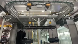
Modern production lines, assembly stations, and warehouse crane installations frequently deploy two or more hoist trolleys on a single I-beam or box-girder runway. Whether electric chain hoists feeding sequential work cells, wire rope hoists handling large fabrications in tandem, or manual hoists assisting ergonomic tasks, the presence of multiple moving loads on one track introduces a critical safety hazard: collision. Uncontrolled contact between trolleys can cause structural damage, load swing, injury to personnel, and costly downtime. Equally important, the ends of the runway must absorb the kinetic energy of a moving hoist if it overtravels, making properly sized and positioned buffer stops indispensable.
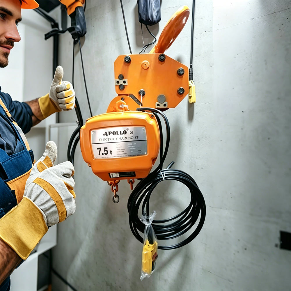
Establishing an effective anti-collision and buffer system demands more than simply placing rubber blocks between hoists. It requires a methodical approach that aligns hoist control logic, mechanical interfaces, and energy absorption capacity with the specific operational envelope. As one of the experienced hoist manufacturers and electric hoist manufacturers, Hangzhou Apollo Lifting Equipment Co., Ltd. has guided international clients through hundreds of multi-hoist projects, from automated warehouse overhead cranes to manual monorails in steel mills. This technical guide provides a comprehensive, engineering-focused framework for selecting, positioning, and integrating anti-collision devices and end-of-track buffers, helping plant engineers and procurement professionals build safer and more productive lifting environments.
2. Problem Overview – Collision and Overtravel Risks on a Common Runway
When multiple hoist trolleys run on the same beam, they share a confined lateral space. Even with attentive operators, simultaneous commands, line-of-sight limitations, or control system lag can bring two trolleys dangerously close. The consequences range from minor paint scuffs to catastrophic cascading failures:
-
Mechanical impact between trolleys: Direct metal-to-metal contact deforms trolley frames, bends wheel axles, and can dislodge anti-drop plates.
-
Load sway amplification: A sudden stop from an unplanned collision induces pendulum motion, risking collision with station operators or adjacent equipment.
-
Chain or rope payout interference: If a hoist is pushed from behind while its hook is loaded, slack in the lifting medium can cause overwrapping or bird-caging.
-
Runway end collision: If a trolley approaches the beam end at full speed without adequate buffering, the impact can fracture the runway support structure or shear the end stop.
Leading overhead crane manufacturers and crane hoist manufacturers agree that multi-hoist runways must be treated as coordinated systems, not as a collection of independent devices. This systemic view aligns with international standards—EN 14492-2 for hoist trolleys prescribes end stops and buffer design, while ISO 13849 addresses safety-related control functions including anti-collision. Hangzhou Apollo integrates such compliance requirements into its design reviews, ensuring that every electric chain hoist or wire rope hoist leaving the factory is prepared for integration into a safe multi-hoist configuration.
3. Key Considerations for Anti-Collision and Buffer Design
Before selecting specific devices, the system designer must assess several interrelated factors:
-
Hoist travel speeds and acceleration: The kinetic energy to be absorbed by a buffer grows with the square of velocity. A hoist moving at 20 m/min may require a buffer four times less capable than one at 40 m/min, assuming equal mass.
-
Trolley weight plus rated load: Buffers are sized for total traveling mass. Many hoist suppliers provide trolley dead weight data and total mass under load to aid buffer selection.
-
Number of hoists and operating logic: A three-hoist system where only one travels while others are stationary presents a different risk profile than a system where two hoists can close in from opposite directions simultaneously.
-
Control type: Pendant vs. radio remote vs. fully automated. A manually controlled hoist relies heavily on operator reaction; automated hoists can leverage sensors and programmed deceleration zones.
-
Environmental conditions: Dust, moisture, extreme temperatures, or chemical exposure affect the durability and selection of electronic sensors and buffer materials.
-
Beam structure and end stop attachment: The runway itself must withstand buffer reaction forces. Hoist manufacturers often recommend a reinforced end connection when heavy high-speed hoists are deployed.
Understanding these variables separates top hoist manufacturers from commodity vendors. Hangzhou Apollo, for example, captures such parameters in a pre-engineering questionnaire that accompanies every multi-hoist order, converting customer-provided data into a detailed anti-collision and buffer specification.
4. Anti-Collision Solutions – Technologies and Comparisons
Anti-collision devices for hoist trolleys can be categorized by operating principle: mechanical contact, inductive proximity, optical ranging, and radio-frequency logic. Each has distinct advantages and limitations.
4.1 Mechanical Limit-Switch Arms and Contact Bumpers
The simplest form of anti-collision is a spring-loaded or rigid arm that actuates a limit switch when pressed by an adjacent trolley. This switch cuts power to the travel motor or signals a warning.
-
Pros: Cost-effective, failsafe (direct contact), easy to integrate with pendant control.
-
Cons: Requires physical contact; may not prevent high-speed collision if the switch triggers too late; subject to mechanical wear and misalignment.
This method is common on manual push-travel trolleys and light electric hoists, supplied by many general hoist suppliers.
4.2 Inductive and Magnetic Proximity Sensors
Non-contact sensors detect the metal mass of an approaching trolley. They trigger at a set gap—typically 50 to 200 mm—allowing the control system to initiate deceleration before contact.
-
Pros: No physical wear; can be encapsulated for harsh environments; fast response.
-
Cons: Sensing distance limited; may require a target plate to be mounted on the adjacent trolley; subject to interference from nearby steel.
Many chain hoist manufacturers offer plug-in inductive sensor brackets as options for their electric chain hoists.
4.3 Photoelectric and Laser Distance Sensors
Laser time-of-flight or photoelectric retro-reflective sensors measure exact distance between trolleys. This enables staged control: a “warning zone” decelerates the hoist, a “stop zone” cuts travel power, and a final mechanical buffer handles residual motion.
-
Pros: Precise, programmable zones; supports smooth deceleration, reducing mechanical shock; ideal for automated systems.
-
Cons: Higher cost; sensitive to dust, paint overspray, and alignment; requires clean lens.
Leading electric hoist manufacturers have begun integrating laser anti-collision modules as factory-fitted options. Hangzhou Apollo provides such advanced sensing packages, pre-calibrated to the customer’s desired stopping distances, simplifying on-site commissioning.
4.4 Wireless/RFID-Based Interlocking
For larger systems where hoists are controlled by a central PLC, RFID tags or wireless beacons can establish geofencing. As a hoist enters a predefined zone relative to another trolley, the control system orchestrates speed reduction or interlocks.
-
Pros: Scalable to many hoists; no line-of-sight limitations; logs collision events for predictive maintenance.
-
Cons: Requires PLC infrastructure; higher initial engineering.
For complex projects—such as warehouse overhead crane runways with three or more hoists—overhead crane manufacturers increasingly implement this approach. Hangzhou Apollo collaborates with industrial automation partners to deliver turnkey radio-controlled anti-collision logic.
Comparative Summary
| Technology | Detection Range | Contact Required? | Suitability for Multiple Hoists |
|---|---|---|---|
| Mechanical limit switch | 0 mm (contact) | Yes | Fair; simple systems |
| Inductive sensor | 5–50 mm | No | Good; robust environments |
| Laser distance sensor | 0.1–20 m | No | Excellent; automated/high-speed |
| Wireless/RFID zonal interlock | Programmable (meters) | No | Excellent; multi-hoist PLC-based |
The choice of technology should align with the operational duty cycle, environment, and budget. As a full-service crane hoist manufacturers partner, Hangzhou Apollo assists clients in selecting the optimum solution and can deliver hoists pre-wired for the chosen anti-collision system.
5. End Buffer Requirements – Absorbing Energy Safely
While anti-collision devices prevent hoist-to-hoist contact, buffers (end stops) protect against runway overtravel. A buffer must be capable of absorbing the kinetic energy of a fully loaded hoist traveling at maximum speed, without transmitting destructive forces to the runway structure.
5.1 Energy Calculation and Buffer Sizing
The kinetic energy to be absorbed is:
E = 0.5 × m × v²
Where:
-
m = total traveling mass (trolley + hoist + load) in kg
-
v = maximum travel speed in m/s
Additional energy from gravitational components on sloped runways must be added. The buffer’s rated energy capacity (E_c) must exceed E, and the buffer stroke (s) must limit the deceleration force (F) to a value tolerated by the beam and support structure:
F ≈ E / s (assuming constant deceleration, simplified)
For instance, a 5-tonne loaded electric wire rope hoist traveling at 20 m/min (0.33 m/s) has E ≈ 272 J. A polyurethane buffer with a 50 mm stroke yields an average force of approximately 5.44 kN, which most IPE 300 beams can easily withstand. However, increase speed to 40 m/min, and E quadruples to 1088 J, requiring a buffer with either longer stroke or hydraulic energy dissipation. Many electric chain hoist installations operate at moderate speeds, making industrial-grade polyurethane buffers from crane parts suppliers sufficient.
5.2 Buffer Types
-
Elastomeric (polyurethane/rubber) buffers: Low cost, progressive stiffness, good for moderate energy. Hangzhou Apollo supplies matched buffer sets for its hoists, with hardness selected for the hoist class.
-
Spring buffers: Metallic coil springs; can handle higher energy, but store and return energy, potentially causing rebound. Suitable where rebound is acceptable.
-
Hydraulic buffers: Oil-filled dampers provide controlled deceleration with minimal rebound. These are preferred for heavy lifting solutions, mining operations, and high-duty-cycle cranes. They require regular maintenance but offer excellent energy absorption per unit stroke.
-
Friction or shear-type buffers: Used in specialized large cranes; less common for monorail hoists.
5.3 Positioning and Installation
Buffers must be mounted at the absolute ends of the runway and, in some cases, on each trolley. If anti-collision systems fail, trolley-mounted buffers provide a final mechanical safeguard. The best practice is a layered protection:
-
Electronic deceleration zone (laser/proximity sensor).
-
Control system final limit switch cutting travel motor power.
-
Runway-end buffer absorbing remaining kinetic energy.
-
Backup trolley-mounted buffer for peer-to-peer contact.
Hoist suppliers should provide clear dimensional drawings showing buffer projection and required space for full compression. Hangzhou Apollo includes detailed buffer integration schematics with every hoist shipment, reflecting the diligence of top hoist manufacturers.
6. Integration with Hoist Controls and Power Supply
Anti-collision devices must interface with the hoist’s travel drive. Modern electric hoists—especially those from electric hoist manufacturers with VFD (variable frequency drive) control—allow multi-level deceleration ramps triggered by sensor inputs. A typical integration scheme:
-
Caution zone sensor (e.g., laser at 3 m): Hoist decelerates to creep speed (e.g., 20% of max).
-
Stop zone sensor (e.g., laser at 1 m): Hoist travel power cut; brake engages.
-
Overrun buffer contact (mechanical): Physical energy absorption.
For manually controlled hoists, a simple relay-based circuit can cut power when a limit switch or inductive sensor is activated, with an override button permitting intentional slow approach for tandem lifting. When multiple hoists are controlled by a single radio remote or pendant, the control system must be configured to prevent conflicting travel commands. Experienced crane hoist manufacturers can supply hoists with pre-engineered interlock cabinets, eliminating risky field wiring.
Power supply for the runway also deserves attention. If hoists are powered by a common enclosed conductor bar or festoon, segmenting the supply with isolators and ensuring that an anti-collision stop does not cut power to the lifting function is critical. Hoists from leading chain hoist manufacturers are designed such that the lifting circuit remains live even when travel is inhibited, allowing operators to raise the load clear before resolving a blockage.
Hangzhou Apollo’s engineering team verifies the electrical interface logic during pre-delivery inspection, ensuring that the anti-collision sensors, VFD parameters, and customer’s control scheme function as a unified system. This service orientation differentiates genuine hoist manufacturers from simple distributors.
7. Best Practices for Reliable Multi-Hoist Runway Design
7.1 Define Safe Working Distances Systematically
Calculate minimum safe stopping distance (including reaction time of controls and brake actuation) and set sensor triggering distances with a safety margin of at least 1.5 times that distance. Always assume worst-case load and speed.
7.2 Use Redundant or Diverse Anti-Collision Measures
A single sensor can fail. Where the consequence of collision is high (e.g., heavy lifting in steel mills or electric hoist for mining operations), combine a laser distance sensor with a mechanical limit switch acting on an independent relay. This principle follows safety integrity levels (SIL) or performance levels (PL) per ISO 13849.
7.3 Standardize Trolley Geometry
When sourcing hoists from multiple hoist suppliers, confirm that the trolley frames and sensor mounting heights are compatible. Inconsistent wheel flange elevations or sensor bracket positions will render anti-collision devices ineffective. Specifying all hoists from a single electric chain hoist supplier, such as Hangzhou Apollo, ensures dimensional uniformity.
7.4 Commissioning and Validation
Before production use, physically test collision scenarios:
-
Run hoist A into a stationary hoist B; verify that the collision sensor triggers and travel stops before contact.
-
Run both hoists towards each other at full speed; confirm that both decelerate and stop.
-
Test end buffer by driving a fully loaded hoist into it at creep speed, then at increasing speeds up to maximum, monitoring buffer compression and structural response.
Document all test results. This rigorous approach is standard practice for top hoist manufacturers during turnkey installations.
7.5 Operator Training and Periodic Inspection
Operators must understand the anti-collision zones and know not to override them except under strict lock-out/tag-out procedures. Inspect buffer elements for cracking, permanent set, or chemical attack every 3-6 months. Check sensor alignment and clean lenses weekly. Hangzhou Apollo provides maintenance checklists and remote support to help customers sustain system integrity.
8. Future Trends in Anti-Collision and Buffer Technology
As industrial lifting evolves toward digital integration, the management of multiple hoists on a single runway is becoming smarter and more predictive.
-
Sensor fusion and edge computing: Combining laser, ultrasonic, and inertial sensors on the trolley with on-board processing enables predictive braking curves that minimize cycle time while guaranteeing separation.
-
Wireless mesh communication: Hoists exchange position, speed, and intent in real time, allowing decentralized anti-collision decision-making. This is particularly beneficial for overhead crane manufacturers deploying fleet-based crane systems in large warehouses.
-
Energy-regenerative buffers: Emerging hydraulic buffers can convert impact energy into electricity, feeding it back into the building grid or hoist battery system, aligning with sustainability goals for heavy lifting solutions.
-
Digital twin simulation: Before installing physical buffers, plant engineers can simulate collision events in a virtual model to optimize sensor placement and buffer stroke. Leading crane manufacturers are offering such simulations as part of their engineering services.
-
Self-diagnosing buffers: Smart buffers with embedded strain gauges and temperature sensors report their health status to the CMMS, triggering maintenance before they degrade.
Hangzhou Apollo is actively integrating select smart technologies into its product roadmap, ensuring that customers investing in electric chain hoist fleets benefit from future-ready safety architectures without being locked into proprietary closed systems.
9. Conclusion – Systematic Safety for Multi-Hoist Operations
Operating multiple hoist trolleys on a single runway is an efficiency multiplier, but it demands an engineered safety layer. Selecting the right anti-collision sensors—whether mechanical, inductive, laser, or wireless—and pairing them with correctly sized buffers transforms a collision-prone arrangement into a reliably orchestrated system. Neglecting these measures, conversely, invites accidents that no responsible hoist manufacturers or hoist suppliers would endorse.
As a comprehensive electric hoist manufacturers, chain hoist manufacturers, and crane hoist manufacturers, Hangzhou Apollo Lifting Equipment Co., Ltd. brings decades of cross-industry expertise to every project. Our team assists clients from initial runway survey through control system integration, ensuring that every electric chain hoist we deliver is ready to coexist safely with others on the same beam. We pair robust mechanical design with advanced sensing options, precise buffer sizing, and global service support—making us a trusted partner among top hoist manufacturers and overhead crane manufacturers worldwide.
Safeguard your multi-hoist runway with expert guidance. Contact Hangzhou Apollo Lifting Equipment Co., Ltd. today to discuss your specific application, receive a tailored anti-collision and buffer proposal, and experience the confidence that comes from working with specialists who understand that true productivity is built on safety.