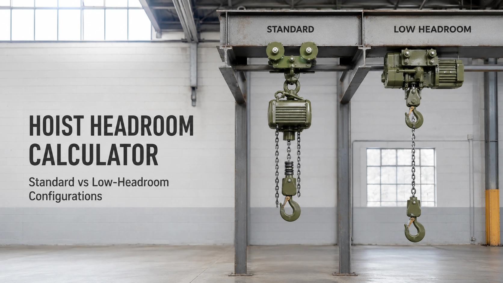
A hoist headroom calculation answers a practical layout question: how high can the hook reach after the trolley, hoist body, beam, and rigging occupy space above the load? The usable lift is controlled by the distance from the supporting beam or runway to the hook, commonly called the headroom or hook approach dimension. A standard configuration may be adequate in an open bay. A low-headroom configuration becomes valuable when roof structure, ductwork, mezzanines, or process equipment leave little vertical clearance.
What headroom means in a hoist layout
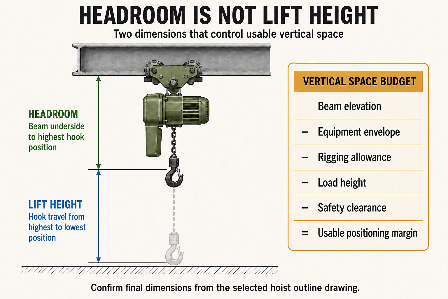
Headroom is not the same as lift height. Lift height is the vertical travel available to the hook or load. Headroom is the portion of the building envelope consumed before the hook begins its useful travel. Two hoists with the same rated capacity and lift may therefore deliver different usable clearance if one has a taller body or a larger trolley arrangement.
For an initial estimate, measure from the underside of the runway beam or monorail support to the highest obstruction below the roof, then subtract the hoist and trolley envelope, the required hook approach, and a safety allowance. The exact dimensions must come from the selected manufacturer drawing. A calculator is a screening tool; it is not a substitute for a certified layout or structural review.
A simple hoist headroom calculation
Use this worksheet for a first pass:
• Available structural depth = beam underside elevation minus the highest fixed obstruction.
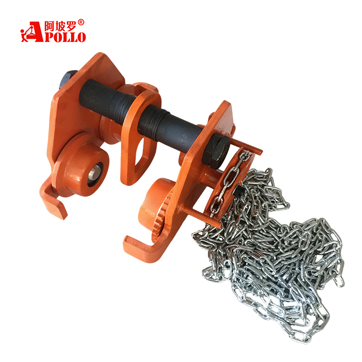
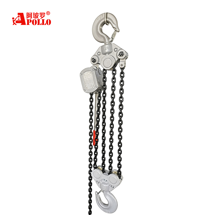
• Equipment envelope = hoist body height plus trolley, end-truck, or suspension dimensions shown on the outline drawing.
• Rigging allowance = hook, sling, spreader, lifting beam, and any minimum clearance required above the load.
• Usable hook travel = available structural depth minus equipment envelope minus rigging allowance.
Example: if the underside of the beam is 18 ft above the floor, the hoist/trolley envelope is 2.1 ft, and the rigging allowance is 1.4 ft, the preliminary hook elevation is about 14.5 ft before considering the load geometry. If the load is 10 ft tall, only about 4.5 ft remains above the floor for positioning. Always add the project-specific clearance required for sway, access, and safe attachment.
Standard vs low-headroom configurations
| Factor | Standard configuration | Low-headroom configuration |
| Vertical envelope | Uses a conventional hoist and trolley arrangement; requires more space above the hook. | Positions the hoist close to the beam or uses a compact trolley to reduce the beam-to-hook distance. |
| Usable lift | Works well where the building has generous clear height. | Recovers useful lift under low roofs, mezzanines, and process lines. |
| Layout trade-off | Often simpler to specify and service when clearance is not constrained. | May involve a specialized trolley, altered wheelbase, or different maintenance access. |
| Selection risk | A tall body can reduce hook approach unexpectedly. | Compact geometry does not remove load, rigging, structural, or inspection clearances. |
When a low-headroom hoist is the better fit
Choose a low-headroom arrangement when the measured hook elevation cannot meet the process requirement with a standard trolley, or when raising the building structure is impractical. Typical triggers include a shallow roof bay, a crane runway installed below utilities, a production line that needs the load close to the ceiling, and a replacement project where existing runway elevations cannot move.
The decision should consider more than the smallest advertised dimension. Compare rated capacity, duty cycle, lift and travel speeds, hook approach on both sides of the beam, trolley wheel clearance, brake and limit-switch access, inspection points, and the path needed to remove the motor or gearbox. A compact arrangement that cannot be maintained safely may create more downtime than it saves in height.
How to measure an existing bay before ordering
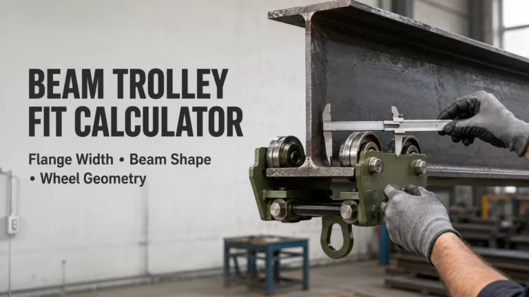
Take measurements with the runway unloaded and record the reference point for every dimension. Measure floor-to-beam height, beam flange width and depth, the distance to roof steel or utilities, the required hook elevation, and the maximum load height. Photograph obstructions and note whether the trolley must pass over splice plates, brackets, or changes in flange width.
Then map the complete load path: hook, below-the-hook device, load center of gravity, and any doors or guarded areas the load must clear. Include the minimum approach needed to place the load at the far end of the bay. If the runway is existing, have its rated capacity, wheel loads, end stops, and supporting steel verified independently of the hoist quotation.
Chain hoist or wire rope hoist?
The lifting medium changes the geometry. An electric chain hoist may offer a compact body for many moderate-capacity applications, while a wire rope hoist may be selected for higher capacities, longer lifts, or crane-duty arrangements. Neither statement is universal: drum diameter, reeving, motor position, trolley design, and the required duty class determine the actual envelope. Apollo’s electric hoist product category includes electric chain, wire rope, winch, and specialty configurations. Its electric chain hoist category is a useful starting point, but the outline drawing for the exact model remains decisive.
Procurement checklist for a headroom fit check
• Send the measured beam elevation, flange dimensions, obstructions, and required hook elevation.
• State rated load, lift height, lift speed, travel speed, starts per hour, and expected duty cycle.
• Ask for certified outline dimensions, hook approach, wheel loads, and the minimum maintenance removal space.
• Confirm voltage, phase, frequency, control method, brake arrangement, limit switches, and overload protection.
• Request a drawing showing the load, sling or spreader, and the required clearance at the highest point.
• Record assumptions and require written confirmation of any nonstandard low-headroom configuration.
Apollo identifies OEM and ODM service support for lifting-equipment projects. That can help when the standard catalog envelope does not fit the measured bay, but any customized dimension, trolley arrangement, or control package must be checked against the project’s structural and safety requirements.
Conclusion
A hoist headroom calculator is most useful when it turns a building measurement into a documented equipment question. Start with the beam and obstruction elevations, subtract the selected hoist and trolley envelope, then include hook, rigging, load, maintenance, and safety clearances. Standard configurations suit open bays; low-headroom configurations can recover valuable lift in constrained spaces, provided their capacity, duty, structure, and service access are verified from the final drawing.
FAQs
Is headroom the same as lift height?
No. Headroom is the space consumed above the hook by the support, trolley, and hoist. Lift height is the useful vertical travel available to the load.
How much clearance should I add to a headroom calculation?
Use the project’s required rigging, load, sway, access, and inspection clearances. Do not use a generic allowance when the manufacturer drawing or site standard specifies another value.
Are low-headroom hoists only for electric chain hoists?
No. Low-headroom arrangements can be designed around chain or wire rope systems. The correct choice depends on capacity, lift, duty, speed, geometry, and maintenance access.
What drawing should a supplier provide?
Request an outline drawing with beam interface, hook approach, overall envelope, wheel loads, hook elevation, service clearances, and the stated operating assumptions.
For a project-specific fit check, contact Apollo’s technical team with the beam dimensions, required hook elevation, load, lift, duty cycle, environment, and a marked-up layout or drawing.